.svg@webp)
How to use an RTK Drone as a GNSS Rover?
 Lukas
Zmejevskis
Lukas
Zmejevskis
We explored the pros and cons of using an RTK drone and GNSS rover ground control points for accurate aerial photogrammetry referencing in another article. Not unexpectedly best results were achieved using both sources for referencing simultaneously. As we classified the RTK drone and the GCP device both as rovers, an obvious question is: Can you use the RTK drone itself to measure GCPs?
GNSS Rover vs. Drone Rover
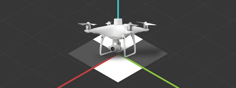
The main difference between the drone and the stick rovers is that the drone flies. They both operate similarly and connect to the same base stations. Another difference is, of course, the physical implementation. The actual rover device is the “head” of the stick, which contains all the electronics. The stick portion of the device is so the rover would be higher off the ground when taking measurements and be more practical to use. The measurement readings are, of course, offset by the length of the stick. Similarly, readings are compensated in the RTK drone to match the camera center. We must keep this in mind.
Small inconvenience
Another operational difference between these rovers is how they save the data. RTK drones only can write the RTK data to the images, while dedicated RTK rovers can store and export data into many ready-to-use formats or even sync the data to the cloud. We will have to devise a way to extract the data from the photos.
GCP Amount and Distribution
Before we attempt to obtain GCPs with our drone, we have to brush up on best practices when measuring ground control points:
Amount of GCPs:
The number of needed GCPs depends on project accuracy requirements. Three ground control points visible in each image would yield the most accurate referencing results. It would require measuring tens or even hundreds of ground control points on larger projects. However, this would be most applicable if we used a non-RTK drone with the usual GPS level errors. With the RTK drone data, we can afford only to have 1 GCP visible in all photos.
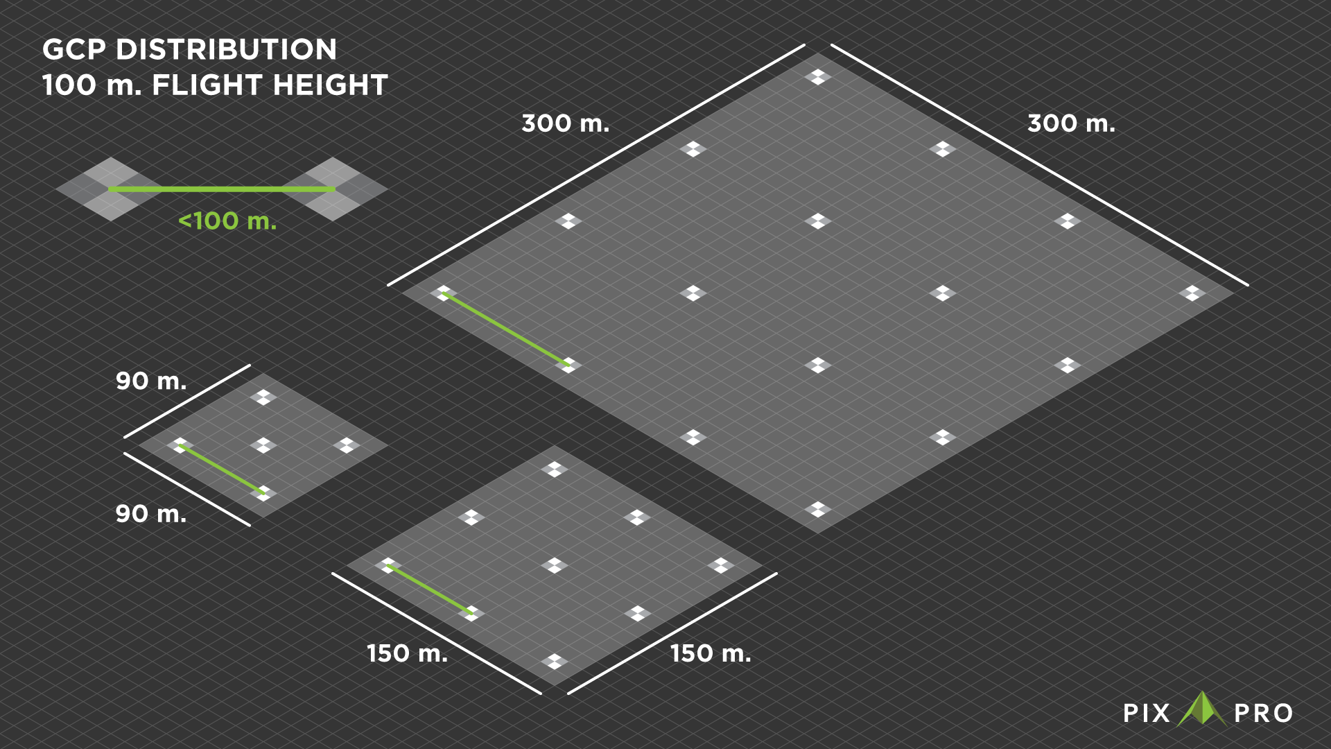
To achieve the required GCP to photos ratio, we can follow a simple rule – keep the distance between ground control points the same or less than the flight height. So if you are planning to fly at 100 meters altitude, take 100 steps between GCPs, which would suffice with RTK drone data. When using a non-RTK drone, apply the same rule but divide the distance by 3. And lastly, always use at least 5 GCPs even if it overrides the method described above.
Distribution of GCPs:
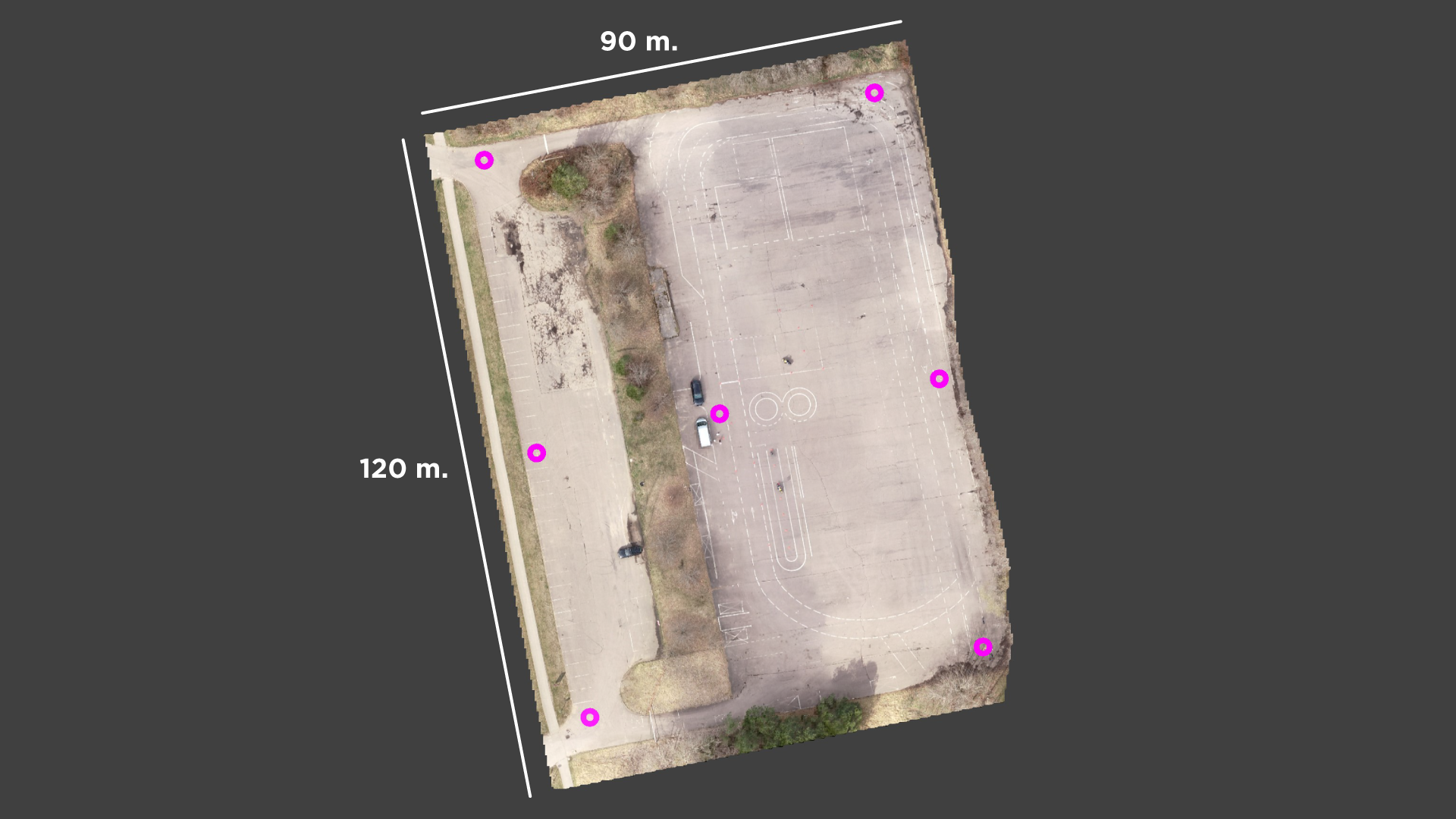
The distribution of the GCPs depends on the accessibility of the scanned area. Still, generally, you want to distribute the ground control points equally in a grid-like structure, following the rule described above. Begin by placing the first GCP in the scanned area corner and walking the required distance parallel to a single side. Do not place the GCPs in the very corner or on the edge of the site; leave a few meters of a buffer zone.
If the area is only slightly larger than the chosen flight height and a grid cannot be regular, place the middle GCP approximately in the middle part of the edge and follow the grid pattern. More GCPs are better than less. If the area is shorter or narrower than the flight height – use 5 GCPs in the familiar dice pattern.
If you are not sure how large is the area you are scanning, the easiest way to measure said area would be to use your drone. Take off at the location of the first GCP and fly to the edge of the site. You will see the distance between you and the drone. Then you will have an idea of how many steps to take to make your grid work. Remember – if unsure – produce more ground control points than necessary. Doing a bit more work now is better than redoing everything later.
GCP Measuring Process
The process of measuring ground control points begins with the distribution of the markers, as described in the previous section. Once the markers are in place, turn on your drone and ensure all the connections are solid. Make sure the IMU and the Compass are in good status and calibrated. Confirm the propellers are NOT attached to the drone. Face the camera directly down and bring the drone to the first marker. Keep the drone above your head when carrying it so your body will not interfere with the signals from the drone. Place the drone so the camera is precisely above the center of the marker and step away from the drone.
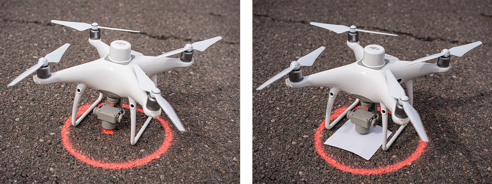
We can either take a single image to represent the GCP in that spot or take many photos and use their information to average the position. The latter method is better because there are some fluctuations even if the drone is still. The important thing is consistency. We will have to recognize the images for each GCP later in post-production, so we must have a way of doing that. Therefore each GCP must have a fixed number of photos taken for it so we can keep track (for example, 10). Another way to ensure each GCP is easily differentiable is to color code the images. Place a piece of colored paper underneath the camera for each GCP, and you will see different colors in the thumbnails. Even with color-coding, I would recommend taking the same amount of photos for each GCP.
After the GCP survey is complete and all markers have their respective photos taken, it is time to fly. Scan your area with the same drone at the height you have chosen prior and take all the data to your computer.
Post-production
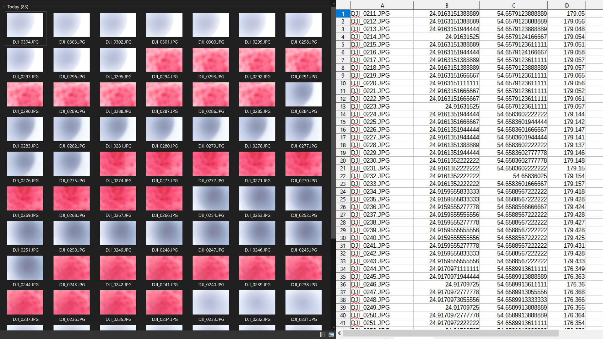
After the work in the field is complete, we find ourselves in possession of an image set for conversion to a file usable in photogrammetry software. Suppose you have color-coded or taken a fixed amount of pictures; that should be easy. You can see different colors in thumbnails and numerical progression in file names.
We have created a simple python program that writes all GPS metadata to a text file to extract the data. Then we can use this text file as a GCP file or open it with an excel type editor to average out the coordinates in case we have multiple files for each GCP. A basic understanding of Excel is necessary to complete such a task.
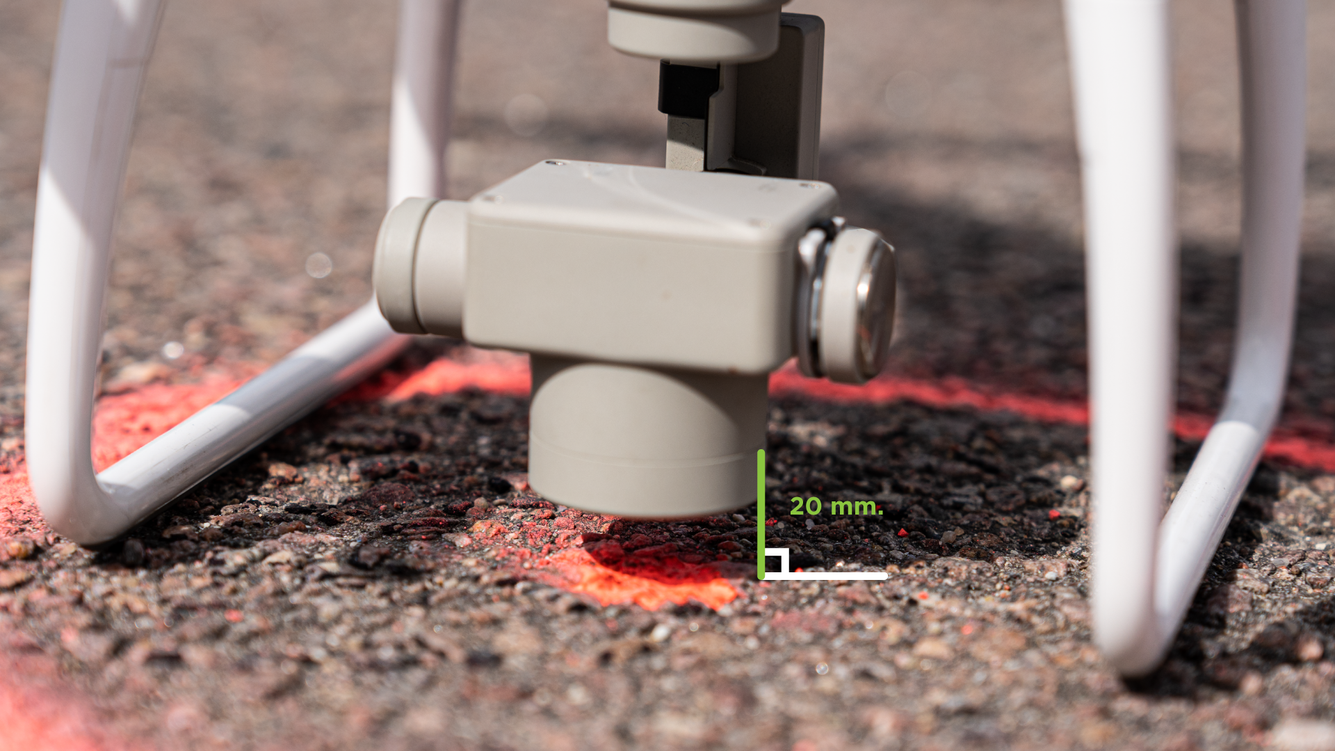
With only the average values left, we must offset our Z-axis value by a drone-specific amount. Earlier, we mentioned that the camera center is the point of reference for the values. As the camera is hanging above the GCP marker when taking measurements, we need to reduce the altitude values by the same amount. In the case of Phantom 4 RTK, the camera lens center is 20 millimeters above ground. So we subtract the 2 centimeters from the altitude values of all GCPs.
An additional conversion could be necessary depending on the processing settings and the data you acquired. For example, matching the ellipsoidal height of these coordinates may require converting the values with capable software. Also, converting to another coordinate system might be necessary if your job requires you to do so. Otherwise, we are ready to use these values in an aerial photogrammetry project.

Results
As a result, we have a GCP file ready to be used for reference in any photogrammetry software. In Pixpro, we have perfected the GCP workflow, so it takes as little time as possible to project GCPs, and the learning curve is very forgiving. Once the work is complete, you should have a photogrammetry project with accurate positioning and perfect reconstruction.
Photographer - Drone Pilot - Photogrammetrist. Years of experience in gathering data for photogrammetry projects, client support and consultations, software testing, and working with development and marketing teams. Feel free to contact me via Pixpro Discord or email (l.zmejevskis@pix-pro.com) if you have any questions about our blog.
Related Blog Posts
Our Related Posts
All of our tools and technologies are designed, modified and updated keeping your needs in mind
Accuracy of Your Photogrammetry Project
Accuracy in photogrammetry is a multifaceted point of discussion. We can talk about absolute, relative, or even geometric accuracy, to name a few. No tool or technique can really prove anything beyond reproach.
Buying a Used Drone - Mavic 2 Pro in 2024
Buying used gear is an excellent way to save money and obtain something that may not be on sale anymore. With drones reaching the 4th or 5th technological generation, the used drone market is becoming more extensive.

Photogrammetry Processing - Common Hardware and Software Issues
Photogrammetry requires complex processing and data crunching to turn photos into 3D models. We need a powerful machine to run the software and all its processes. Not only that, but the software within our machine may impact the performance of photogrammetry software in various ways.
Ready to get started with your project?
You can choose from our three different plans or ask for a custom solution where you can process as many photos as you can!
Free 14-day trial. Cancel any time.